"Сила Ампера" Українською Мовою
Why such a postulate as the Ampère force, which is one of the constants of physics, I singled out in a separate article. To do this, you need to repeat or double-check, for example, the corresponding chapter from a physics textbook: CHAPTER TWO. MAGNETS. A MAGNETIC FIELD. MAGNETIC ACTION OF THE CURRENT, For further clarification, we study / repeat: THE MAGNETIC FIELD AFFECTS A CONDUCTOR WITH CURRENT.
The constant that is used in the equation according to the Mitkevich rule (link to the source of information on the slide ELECTRICAL ENGINEERING IN "CHILDREN" DRAWINGS, or the site FREE ENERGY (https://001-lab.at.ua/index/osnovy_ehlektrotekhniki/0) -13-0 -13).

Formulas for active power:
P = U I — in DC circuits;
P = U I cosθ — in single-phase AC circuits;
The power transmitted to the load will be:
P = U (voltage at the generator terminals with the load connected) * I (current in the circuit)
P load = 4 V * 1.3 A = 5.2 W, which in no way corresponds to the full power of the generator.
Let's check the fulfillment of Mitkevich's rule in practice. Guy mich, conducted an experiment for me with a simple generator:
https://www.youtube.com/watch?v=VAM9TLfUDkQ


Т = P * 9.55 / rpm,
[https://www.kjmagnetics.com/calculator.asp?calcType=block]

Trying to calculate the electromagnetic torque:
T = F * r = N * (B * l * I) * r = 15 turns * (0.1307 T * 0.66 m * 1.3 A) * 0.055 m = 0.093 N * m.
The electromagnetic torque figure is wonderful, as the converter efficiency will be
COP = 0.093 / 0.099 = 0.94 (94%).
SECOND METHOD: Let's calculate the electrical power from the data obtained. Let's find the value of magnetic induction from the EMF formula: E = Bm*l*v. It is necessary to find the rate of change of magnetic flux, we find it from the formula:
v = π*r*rpm/30 = 3.14 * 0.055 * 2000 / 30 = 11.51 m/s.
We also need to find the magnitude of the EMF. Let's find the dimension of the voltage drop:
Ui = I*R = 1.3A * 3 ohm = (3.99) 4V,
add it to the voltage at the generator terminals and get the value of EMF (E) in the generator phase:
E = Ug + (I*R) = 4 + 4 = 8 V. (which is much less than the real EMF).
We still have winding resistance r = 1 Ohm
E = Ug + (I*(R+r0)) = 4 + (1.3*(3+1)= 9.2 V.
Which is again much less than the real EMF by (10.4 - 9.2) = 1.2 V.
If there are already 15 turns, there are reactive losses in the interscrew interaction, you can calculate the reactive resistance by the formula
Rz = U/I = 1.2 V / 1.3A = 0.923 Ohm
Next, we convert the formula EMF E = Bm * l * v to calculate the magnetic induction:
Bm = E / v / l = 10.4 V / 11.51 m/s / 9.9 m = 0.091 T.
From the result we try to calculate the electromagnetic torque:
T = F*r = N*(B*l*I) * r = 15 turns * (0,091 T * 0.66 m * 1.3A) * 0.055 m = 0.078 N*m.
The figure is simply very remarkable COP = 0.078 / 0.099 = 0.79 (79%). Which is also VERY great, but VERY unlikely. Any rotating system and the motor along with it has an idle torque, in this case it is not accounted for, which is virtually impossible. I'm sure if Mitch. had taken measurements of the power consumed by the engine while the alternator was idling at 2000 rpm, we would have an accurate measurement of the error.
Let's find it from the original data T0 = 0.099 - 0.078 = 0.021 N*m. Next we find the idle power:
P0 = M0 * rpm / 9.55 = 0.021 * 2000 / 9.55 = 4.4 W.
In this formula: T = F * r = N * (B * l * I) * r you can only change the value of magnetic induction B. Science shows us the existence of an average Baverage value of magnetic induction. The average value of magnetic induction can be determined from the mechanical power parameter of the generator, which by default should be equal to the electrical power. Pe = Rm = 13.5 watts.
All parameters are known to us. Let's find the resulting Ampere force from the formula T = F*r:
F = T/r = 0.065/0.055 = 1.18 Newton.
Next, we find the value of the resultant magnetic induction from the magnetic induction modulus formula: B = F / (l*I) = F /(N*l)*I
B = F / (N*l)*I = 1.18 / (15*0.66) * 1.3 = 0.091 T
If we take this value of magnetic induction and substitute it into the formula for calculating EMF:
E = Bm*V*l*v* = 0.091 * (15*0.66) * 11.51 = 10.4 V,
the result obtained coincides with that obtained by measuring the voltage at the terminals of the generator of the original data.
Some orthodoxies and keepers of physical constants will object, мол, the magnetic field and its magnetic induction of the magnetic pole of the generator rotor magnetic pole in the conductor zone does not change. This is undoubted, but what then changes to produce the corresponding result of the resultant electromagnetic force?
Let us adopt and write down Mitkiewicz's rule: The electrical power developed by the generator is equal to the converted mechanical power.
Electrical power = Pe = EI = Blv*I = BIL*v = Fv = Pk = Mechanical power
According to this concept, educational resources:
The total electrical power developed by a dc generator is equal to the product of the generator's electromotive force and the total current of its armature winding: P=EIa.
If the generator's EMF is kept constant, its total electrical power will be proportional to the current.
According to the generator EMF formula: E=(p/a)zF(rpm/60).
Other things being equal, the total electrical power of a generator increases with the increase in the number of revolutions of its armature and the number of its poles.
Useful power P1, given by the generator into the external circuit, is equal to the product of the electrical voltage at the terminals of the generator on the amount of current sent by the generator into the external circuit: P1 = UI, where P1 - useful power in watts; U - voltage in volts; I - current in amperes.
Notice anything special? Then let's write down the Mitkiewicz equation in numbers for the simple generator we've looked at:
13.52 W = 10.4 V * 1.3 A = (0.091 T * 11.51 m/s * 9.9 m) * 1.3A =.
= (0.091 T * (1.3A * 15 turns ) * 0.66 m) * 11.51 m/s = 1.76 Newtons * 11.51 m/s = 13.52 watts
Re = 13.52 W = 13.52 W = Pk
For schoolchildren and students (who do not have to deal with the calculation of electrical machines), everything is nicely confirmed, for the grade for the passed material. Only the power of our generator does not have a value of 13.5 W, its value is less than 13.5 W - 5.2 W = 8.3 W. It will be objected that this formula refers to the total power. I object to this contention. The total power of the generator is the sum of the two powers in series connection of the circuit: Generator and Load. The manifestation of current on the load has no effect on the magnetic interaction in the generator. Therefore, the generator power will be equal to 8.3 W without reactive losses even less. Approximately half of the mechanical power without taking idle power into account.
From this we can safely derive the formula that the generator power in the ideal case is equal to:
Pg = 1/2EI

§ 5.16. ANCHOR REACTIONThe magnetic system of a synchronous generator in idle mode (without load) has a magnetic flux of the poles, which induces an EMF in the stator winding. However, after the load is switched on, a current arises in the three-phase stator winding, which, as is known, creates its own rotating field. The rotation speed of this field is equal to the rotation speed of the pole field. Consequently, the total magnetic flux of machines under load consists of the rotor and stator fluxes, but it does not follow that the stator magnetic field always strengthens the pole field. The result of the interaction of these fields is determined by the magnitude and nature of the load.The effect of the stator field on the field of the pole excitation system is called the stator reaction or, by analogy with DC machines, the armature reaction.
Previously, a number of experiments were carried out with the calculation of the traction electromagnetic force of a current-carrying conductor in a magnetic field.
I summarized the data and calculations in the table:

In this experiment, the actual result is also different from the calculated constant. And most importantly, this is a direct dependence on the magnitude of the voltage drop (actually a vortex electric field) in the conductor section in a magnetic field. It turns out that the final value, in the module of the electromagnetic force, remains with the electromagnetic force of the conductor, and not with the external field. If we consider the dimensionality of the values of the magnetic induction of a current-carrying conductor, the resulting electromagnetic force will directly depend on the presence of an electric vortex field around the conductor, it is the value of the magnetic induction around the conductor that will be effective, even if the external field far exceeds the value of the magnetic induction of the conductor available for interaction with an external magnetic field.
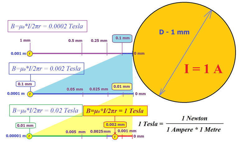
Thus, a constant from a physics textbook, so beloved by orthodox physics and linear engineers:
B (1 T) = F (1 N) / [L (1 m) * I (1 A)],
applicable to a conductor where the voltage drop across a given conductor is absolute or the voltage drop is the voltage (EMF) of the source.
****
If we make a calculation of the real resistance force of the generator discussed above, then we get an expression for the real ampere force from the effective value of the magnetic induction of the conductor, a different expression from the previous ones:
T3 = Fr = N * (Bi l I) * r = 15 turns * (0.079 T * 0.66 m * 1.3 A = 0.067 N) * 0.055 m = 0.055 Nm.
The first expression calculated by us on the magnetic induction exponent, at the calculated value of magnetic induction from the pole of the magnet, at the point of the conductor:
T1 = Fr = N * (Bm l I) * r = 15 turns * (0.129 T * 0.66 m * 1.3 A = 0.11 N) * 0.055 m = 0.091 Nm.
The second value, according to the RMS value of the magnetic induction based on the RMS value of the EMF measured by the ammeter. This value is used to calculate the electromagnetic torque of the generator in practice.
T2 = Fr = N * (B l I) * r = 15 turns * (0.091 T * 0.66 m * 1.3 A = 0.078 N) * 0.055 m = 0.065 Nm.
Let's remember the formula for kinetic energy: Еk = 1/2 mv²
To do mechanical work, half of the potential mechanical energy must be expended. How should we calculate the equilibrium of the kinetic powers of pressure and resistance? What does the value of half (1/2 = 0.5) of the product of mass times the square of velocity mean in the kinetic energy formula ?
In our case there is the driving mechanical power of the motor:
Tm = Pm*9.55 / RPM = 20.68 *9.55 / 2000 = 0.099 Nm
1) For the Ampere force of conductor T3: COP = 0.055 / 0.099 = 0.55
2) For the magnetic induction of the magnet T1: COP = 0.091 / 0.099 = 0.91
3) For the rms EMF of T2: COP = 0.065 / 0.099 = 0.65
Which indicator is closest to the truth?
Dear guests, participants, opponents!
If you can't wait to convince me that I'm wrong or that I've made a discovery, don't bother. I will accept proof of a fallacy, only with an example of an engineering sane calculation that can be verified. I am also not going to take this topic into academia, nor am I going to prove me right to orthodox physicists and engineers. It is enough for me that I have figured it out myself and shared it with you in this publication. To calculate the level of magnetic induction to calculate Ampere's force, it is necessary to derive the coefficient for the resultant magnetic induction from the magnetic induction of the external field from the condition of the voltage drop level on the active section of the wire k'=Ui/E, where: Ui is the actual voltage drop across the circuit, excluding reactance, in volts, E is the initial source voltage, (or the generator idle EMF, in volts). To determine the magnetic induction for the resultant Ampere force, multiply the magnetic induction of the external magnetic field in the conductor area by this factor B = Bm * k'. The resultant magnetic induction of the external magnetic field in the conductor zone can also be calculated from the Ampere force obtained experimentally, from the dynamometer reading, knowing the current strength, the length of the active wire, and two voltage values: the initial and the effective voltage. The explanation is simple: the vortex magnetic field of the conductor, when interacting with the external field, acts only at the boundary of the vortex electric field. The closer this boundary (r) is to the surface of the conductor, the more effective is the magnetic interaction of the conductor with the current and the external magnetic field. This boundary can also be calculated by the formula:
r = (1+k')*μ₀*(I/(2π*Bm)),
further substituting this value into the formula for calculating the magnetic induction for a straight conductor B=μ₀*I /2πr, we get the value of the resulting magnetic induction for the Ampere Force, as well as for the effective voltage of the generator winding under load. Whether it is connected or not is already obvious. If you want to call this coefficient the Rakarsky coefficient, I will not object. All successful research and achievement of the goals and objectives, if they are good.
Best regards, Serge Rakarsky
Link to the original publication: Результирующая Сила Ампера - Free Energy Systems - Каталог статей - FES (narod.ru)
Немає коментарів:
Дописати коментар