Постійний магніт і рівняння Максвелла

Постійний магніт і рівняння Максвелла
ТУРЕЦЬКИЙ МАГНІТНИЙ ГЕНЕРАТОР В ІТАЛІЇ 2019 та інші магнітні системи ...

Давно хотів відредагувати свій старий пост по темі цієї презентації.
Почнемо зі сторінки у Вікіпедії: Магнітний двигун — Вікіпедія
Магнітний двигун або магнітний двигун - це різновид вічного двигуна, який призначений для створення обертання за допомогою постійних магнітів в статорі і роторі без зовнішнього джерела енергії. Такий мотор теоретично і практично не реалізований. Ідею функціонування магнітних двигунів пропагували різні любителі. Це можна розцінювати як псевдонауку. Є часті згадки про вільну енергію, а іноді навіть посилання на езотерику.
Чи так все є насправді?

Джон Ворел Кілі (John Worrell Keely) (1827-1898) зі штату Філадельфія, США, в період близько 30 років експериментував з хвилями та речовиною, для чого експлуатував винайдені ним технічні прилади. Джон Кілі розробив основи теорії вібраційної "музичної" будови матерії. Науку цю він назвав - Sympathetic Vibratory Physics (фізика симпатичних (відповідних чи співчутливих) вібрацій). На основі цієї теорії він і розробляв свою техніку. Прилади Кілі не були схожі на традиційні, тому багато людей його не могли правильно зрозуміти і вважали (та й вважають) фокусником чи чарівником. Однак, це все реальність. Адже саме чарами здаватиметься людині все, що вона не зможе пояснити.
Першим альтернатором був генератор Іполита Піксії 1832

Дуже цікаве питання виникло між мною і рядом переконаних прихильників електромагнітної індукції, коли лінії електропередач перерізають дроти фазних обмоток в електрогенераторах.
Тільки один тип генераторів і подібні до них працювали за принципом перерізання провідника силовими лініями - це генератор Грамма і аналогічні Динамо, де провідник переміщався в проміжку між полюсом електромагніту збудження і сердечником якоря, де обмотка намотується поверх металевої основи якоря.
Про все це я докладно розповів у своїй публікації «Винахід електромагнітного генератора», де власне і констатував, що генератор Pixia (1892) і невідомий Р. М. (1892), який написав листа Фарадею з описом своєї конструкції генератора, працювали за принципом зміни Анапольного моменту, замкнутого магнітного потоку в замкнутому сердечнику.
Високочастотні електричні машини - генератори індукторів з перемиканням потоку магнітного збудження в статорі
Під трифазної системою ЕРС (напруг) розуміють сукупність трьох симетричних ДС, амплітуди, яких рівні за значенням і зрушені (амплітуда кожної ЕРС щодо попередньої амплітуди іншої ЕРС) на один і той же фазний кут. На рис. 1,д наведена схема найпростішого синхронного трифазного генератора струму. Обмотки, ст. яких наводяться змінні ЕРС, поміщені в пази статора, зміщені коло на 120°. Висновкам обмоток присвоєно позначення "початок" АБСа "кінців" X, Y, Z відповідно. По обмотці ротора відбувається постійний струм, створюючи магнітне поле. При перетині обмоток статора магнітним полем ротора, що обертається, в них наводиться симетрична система трьох синусоїдальних ЕРС однакової частоти і амплітуди, зрушених по фазі на 120° (рис. 1,6). За один оберт ротора, що відповідає періоду часу Т, в кожній з обмоток відбувається повний цикл зміни ЕРС. Коли вісь ротора / - / перетинає витки обмотки статора, в них наводиться максимальна ЕРС. Але так як для трьох обмоток статора це відбувається в різні моменти часу, то і максимуми наведених ЕРС не збігаються по фазі, тобто їх амплітуди Ед, Eg, Її виявляються одна з одної зрушеними на 1/3 періоду, або на 120°.
Фаза. Кут, що характеризує певну стадію параметра, що періодично змінюється (в даному випадку ЕРС), називають фазовим кутом або простою фазою. При спільному розгляді двох (і більше) синусоїдально змінюються ЕРС однієї частоти, якщо їх нульові (або амплітудні) значення наступають не одночасно, кажуть, що вони зрушені фазою. Зсув завжди визначають між однаковими фазами, наприклад, між початками синусоїд, як це показано на рис. 1,6 або між амплітудами. При зрушенні двох синусоїд по фазі одна з них відставатиме від іншої за часом. Щоб визначити, яка із синусоїд відстає, знаходять їх початку, тобто нульові значення ЕРС при переході від негативних 6 значень до позитивних.

Мал. 1. Отримання трифазної симетричної системи ЕРС: 1 - статор; 2 - обмотка статора; 3 - ротор; 4 - обмотка ротора
DC machines with semiconductor switches / Information about the material
The collector and brush apparatus of a DC machine constitute a unit that causes difficulties in the design, manufacture and operation of the machine. Hence the desire to replace this unit with a contactless current commutator, which can be accomplished using controlled electric valves, especially semiconductor ones.

Статичні електромагнітні генератори Клементе Фігераса, Роберта Голкомба, Пак Чже Суна та Шодзі Ханеди.
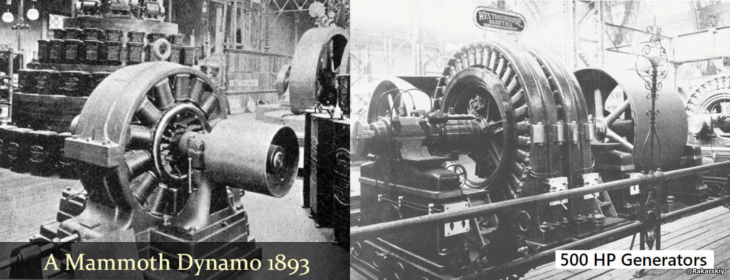
Я припустив, що Клементе Фігера (іспанський інженер) продав ще один патент світовому банку, який нам невідомий. Нам відомі лише два патенти з 1902 року (час продажу Фігерою прав на винахід). Один із замкнутим контуром магнітопроводу, а інший для посилення магнітного поля для рухомого провідника. Всі свої думки з цього приводу я відобразив у відкритій публікації CLEMENTE FIGUERA GENERATOR 1902 . У тій же публікації я припустив, що існує ще одна можлива робоча версія, яка побудована, за аналогією з електричними динамо-машинами та електрогенераторами того часу. Фотографуємо динамомашину та електричний генератор змінного струму з виставки кінця 19 століття.
У квантовій фізиці квантові частинки мають властивість, відому як спин, але на відміну від фізичного обертання планети, квантовий спин є абстрактним, Спін визначає, як такі частинки, як електрони, поводяться в магнітних середовищах. Електрон може мати «спін-верх» або «спін-вниз», але це не простий напрямок — це квантовий стан, який може набувати лише певних значень, наприклад +1/2 або -1/2. Дивно, що обертання квантовано, що означає, що він ніколи не може бути між цими станами. Ця квантова природа спина є основою багатьох передових технологій, від квантових комп'ютерів до МРТ. Розуміючи обертання, ми розкриваємо глибші уявлення про поведінку матерії у найменших масштабах.

