Now, as wrote Dr. Hartmann, some research group from Germany tested it for over-unity, and it is working for 140 W input and 1200 W output, so it is the over-unity system, and it will be patented in Germany. Look text after my paper here or email to Dr. Hartmann.Ф-Machine Alexander V. FrolovPublished at first in New Energy News, USA, June 1994, p.9
From 1994 to present time I can not find any serious investor to patent it for Russia or as International patent. Perhaps you know who is interested? Let do it at last.
Some demonstartion for this idea was made in 1996, look photos and my report from New Ideas in Natural Sciences Conference.
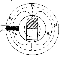
The terms "F-machine" and "F-transformer" are connected with a form of magnetic flux force lines for this type of system.
Fig.1 shows a device that uses permanent magnets as the rotor. The magnetic flux is concentrated in
ferromagnetic ring. The structure of this field consists of two parts. The direction of flux in one part is opposite to the direction of flux in the other part.
The coil L is an ordinary coil of wire. In strength of electromagnetic induction principle the electro-motive force EMF is generated in coil L when rotor is revolving and flux H is changing. If the load is connected to coil L the secondary flux H is created.
The secondary flux tries to compensate any changes of the primary flux. Since in F-machine the secondary flux a created inside the ring it works against the primary flux only on half-period ot the ring, and it is co-directional to the primary flux in the other half-period of the ring.
The total effect of secondary flux is equal to zero.
Fig. 2 shows a similar version of bidirectional operation mode. The coil L1 is loaded with the AC generator. The coils L2 and L3 create two opposite magnetic fluxes H2 and H3 Total effect of creation of power in loads is equal to zero.
The number of secondary coils is not limited. The value of power in one coil is a function of velocity of the primary flux changes similar to conventional calculations. The consolidation of secondary coils to increase total output power is possible after rectification of every current since currents in different coils are not coherent.
The general principle is the creation of a bidirectional power process. It is not possible to get power in load without connection between cause and effect but it is possible to create two opposite effects for one cause.
The total effect is equal to zero in this case.
According to Dr. Aspden this "experiment (his Fig.1) gives the "free energy" answer, but he wrote: "to my surprise, with the coil arrangement shown in (Aspden's) Fig. 2. I found that the free energy becomes available well below the knee of the B-H curve at quite normal flux densities! Even at one-fifth of magnetic saturation levels, the excess free energy potential can exceed the input power and give a twice-unity factor of performance".
Subject: A toroidal overunity generator claim !
Date: Tue, 03 Aug 1999 13:30:18 +0200
From: Stefan Hartmann <harti@harti.com>
Organization: Hartmann Multimedia Service
To: Free Energy <freenrg-l@eskimo.com>,
Newman-L Mailing List <newman-l@emachine.com>Hi All,
a toroidal overunity generator has been build according similar to figure 1 at:
http://www.time-machine.spb.ru/ph-machine.htm
(Not by Mr. Frolov in this case , I just use this picture for reference, the source wants to stay anonymous, until his patent application is done and university verification tests will be done)
The claims are: 1200 Watts coil out with about 1076.4 Watts in into the driving motor at 3450 RPM.
8 amps @117volts at noload
9.2 amps @117 volts at full load
The output of about 1200 Watts is already a total overunity operation !
As they just increase the input power by about 140 Watts only between idle and load state and they get 1200 Watts output it seems indeed a case, where Lenz law is violated ! (the driving motor
is inefficient in this case)
This generator also has NO motor effect ! If you supply current to the coil, the permanent magnet
in the center will not rotate, cause the flux just stays inside the toroid core !
There you can see, that the back drag does not influence the mechanical rotation of the magnet !
Regards, Stefan.
Source: http://alexfrolov.narod.ru/ph-machine.htm
There is a patent for a similar principle:
Single-phase isolation transformer for airfield lighting systems
Patent authors: Novikov M.I., Sintsov S.V., Dygin V.S., Zubarevich N.S
RU28278U1 / 2003-03-10
https://findpatent.ru/patent/219/2199786.html / https://patents.google.com/patent/RU28278U1/ru
1. A single-phase isolation transformer for airfield lighting systems, containing a magnetic circuit with primary and secondary windings, characterized in that the magnetic circuit is made of three rods, while the primary winding is installed on the central rod, and the secondary winding contains two sections that are installed on peripheral rods and are connected between itself in such a way that it is possible to add up the energy received by the sections from the magnetic circuit.
2. The transformer according to claim 1, characterized in that the sections of the secondary winding are connected in series.
3. Transformer according to claim 1, characterized in that the sections of the secondary winding are connected in parallel.
-----
Bi-toroid transformer CA2594905A1 / 2009-01-18 Inventor: Thane Christopher Heins
https://patents.google.com/patent/CA2594905A1/en
The invention provides a means of increasing transformer efficiency above 100%. The transformer consists of a single primary coil and two secondary coils. The two secondary coils are set on a secondary core toroid which is designed to be maintained at a lower reluctance than the primary core toroid throughout the transformer's entire operating range.
When the transformer secondary delivers current to a load the subsequent induced back EMF is not allowed to couple back to the primary due to the higher reluctance flux path.
Instead the secondary coil's induced back EMF follows the path of least reluctance into the adjacent secondary coil.
Our prototype is close to this, but not quite (efficiency is only > 3000%), as can be seen from the data sheets, where the primary current decreases with a decrease in the load of the secondary winding (1 Ohm), and the efficiency drops from 3000%. only up to 146% or so.
Ideally, there should be practically NO REAL POWER in a conventional coil, except for that which is repeated due to the resistance that is observed when the DC is regularly turned on.
An interesting arrangement, again the device's work is divided into two measures: Excitation and Self-induction. If we take into account the author's drawings, the excitation register works like a conventional transformer (the first coil of the secondary circuit works on mutual induction in the first window of the first core). The second core, according to the author's drawings, should induce a field with a second secondary coil that should be connected to the first in series and have enough turns to excite the field that should be composed in the middle core. This coil will act as a load in the secondary circuit. When you somehow switch to the self-induction register, a miracle must happen so that the field in the first core is destroyed, and in the second core, it is switched in the opposite direction, which will lead to generation in the secondary circuit. This can only happen if it is true that self-induction is the conversion of the current around a conductor into an emf in my topology of electrodynamics:
curl E = - dBi / dt
************
Material for students: Transformer converters:
https://studopedia.ru/28_18110_transformatornie-preobrazovateli.html
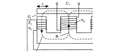
Transformer converters use the change in mutual inductance between the converter windings. On fig. 2.14 shows a differential transformer converter with a flat magnetic core.
On the middle rod of the core is the primary winding, which is powered by an alternating current network. This is the excitation winding. On the extreme rods there are two identical secondary windings connected in series opposite. Transformer emfs are induced in the secondary windings
E 1 = 4,44 fw 1Ф1m; E 2 = 4,44 fw 2Ф2m. (2.19)
The output voltage of the converter in idle mode is equal to the difference in the EMF of the secondary windings:
U out = E 1 – E 2 = 4,44 f (w 1Ф1m – w 2Ф2m) = 4,44 f w (Ф1m – Ф2m).
In the neutral position of the armature, the magnetic flux F, created by the primary winding of the converter, branches into two equal fluxes F1 and F2. Therefore, the output voltage will be zero. The displacement of the armature leads to a change in the magnetic conductivities of the right and left parts of the converter, and, consequently, the magnetic fluxes F1 and F2 proportional to them. So, shifting the armature to the right leads to the fact that Ф2 > Ф1, as a result of which a voltage appears at the output of the converter. When shifted to the left, Ф2 < Ф1, and a voltage appears at the output, the phase of which differs by 180° from the output voltage when shifted to the right.
------------------------------------
US9620280B2 / Energy Management System (Split flow transformer has a primary or input winding, at least two secondary or output coils). /2017-04-11-Publication / Status - Active / 2035-06-02 - Adjusted expiration/ Inventor: William Alek
Results
PLOAD = VLOAD/ILOAD cos (0°) = 0.0499 Watts
PSOURCE = VSOURCE ISOURCE cos (77°) = 0.0392 Watts
COP = PLOAD/PSOURCE = 1.273
These results indicated that the inventive energy management system produced more energy than it consumed so that it can be attached to rechargeable batteries which are thereby constantly recharged. This system can avoid the down-time that many rechargeable battery powered device experience
----------------------
Another implementation of the topology originally proposed by Frolov is the Alexandrov resonant transformer: https://www.youtube.com/watch?v=XdWwqZe4nz8
-----------------------------------------------------------------
One of my options for an asymmetric transformer according to the Ф-transformer system.
To be continued soon!


Немає коментарів:
Дописати коментар