вівторок, 14 червня 2022 р.

Over Unity - Holcomb Energy System

Existing Over Unity System - Holcomb Energy System generator  https://holcombenergysystems.com/. Device for obtaining energy by electromagnetic induction. To enhance the magnetic flux, a method of increasing the magnetic flux in electrical steel due to magnetic permeability is common.

All that was done by Dr. Holcomb is a solution of the original design: where the rotor was replaced, in a traditional electromagnetic synchronous generator with a constant source of magnetic flux (electromagnet), to a solid design, with dynamic switching of the number of electromagnets simulating the rotation of magnetic .

Note that in a synchronous generator, the dynamic rotor is replaced by a solid! There is no physical rotation of bodies, no physical speed.

It is proved that the generator is not a device for converting mechanical energy (Pk = F * v) into electrical energy (Pe = I * U).

If you look at the formulas, it is a statement of modern science, the enlightenment of this postulate - is a fact of the established concept of the absurd.

Ingeniously simple! Synchronous generator is the main source of electricity in electrical networks. Even easier for the household, instead of a mini hydroelectric power plant, windmill or solar panel complex, you need a small solid-state generator.

Dr. Holcomb not only voiced and formalized the idea in patents, but also embodied it in many existing designs. In addition, the device is used on a commercial site.

The question is what else needs to be proved? Trolls are brainwashing the nobility! Even if the gentleman decides to build this device, he will have to study the engineering method of construction. This is a seemingly simple method, without good knowledge and skills you can not master it.

I am glad that Dr. Holcomb was able to implement this idea. I can't believe no one has thought about it before.

The law of conservation of energy does not work in a solid-state generator system.

Magnetism and electricity can not be tied to the physical mass and physical velocity of this mass. Above I gave two formulas of power - mechanical and electrical.

This is the paradox of a device, a synchronous mechanical or solid-state generator. According to the introduction of electric excitation power and obtaining useful amplified power by the consumer, mechanical and solid-state generators are almost identical. We excite with less force, we get more. Amplifier is the ability of "magnetic flux" to accelerate - in the material of electrical steel.

For example, if the magnetic "conductivity" of the magnetic flux of air is equal to 1, the magnetic "conductivity" of electrical steel is 4000.

What it is? This is superconductivity in terms of air conductivity in vacuum. Correctly called magnetic permeability. But this is the initial parameter, followed by magnetic saturation. As the magnetic permeability decreases and the magnetic intensity increases, the conductivity decreases and the magnetic saturation (magnetic induction) is calculated. Magnetic induction has a limit of this saturation, so push more to get more will not work.

This is a good pair of chapters. Although everything is in academic textbooks of physics. This is not a closed science, it is taught in all specialized educational institutions.

https://www.patentguru.com/assignee/holcomb-scientific-research-limited

Conversion rates of solid state generators installed at a US facility by Holcomb Energy Systems. His reports and marketing publications show approximately a conversion rate of 1,3-2.0. Company Publication:

https://holcombenergysystems.medium.com/irrefutable-data-on-the-holcomb-energy-system-in-action-2ff56b0ab451


These graphs, direct from Florida Power & Light’s billing website and corroborated by the HES System meters, verify that when the ILPG system is installed and in-circuit, it delivers an average daily efficiency of 205%. During the day, the lowest efficiency observed is 130% while the greatest efficiency observed is 260% during late afternoons because of the increased building load of the air conditioning system.

There is information that these generators as power amplifiers are already being supplied to customers from the USA. Measurements of conversion capabilities when measured by instruments recommended by NASA https://fb.watch/fMZMcgmLij/


COP = Pout/Pin = 19.86 kW / 2.56 kW = 7.76 (776%)

The "Global Energy Control System" will do anything to shut down this simple technology.

Robert Holcomb's solid state synchronous machine, works on the algorithm of a traditional electromechanical synchronous machine, generating electricity. A solid state rotor is a system of electromagnets that mimic the action of a mechanical magnetic rotor. The task is to create a magnetic excitation flux, hold it and move it in the stator and rotor, synchronously inducing EMF in the generator phases. When a load is connected, the excited current in the phase wires amplifies the magnetic field of the system's magnetic flux. The magnetic flux [ϕ] has a constant component, both for a traditional electromechanical generator machine and for a Holcomb solid state machine. The Holcomb machine, like the synchronous generator, depends heavily on the connected load to create a working rotating field.


How to design a solid state rotor instead of a traditional magnetic rotor!
A feature of rotational modeling, should be a constant component of magnetic induction at the actual poles of the rotor at its conditional motion.

The solid state rotor of Robert Holcomb (also the inventor of Park Jae-sung) works on the algorithm of a mechanical synchronous generator.

First you need to understand how the traditional magnetic rotor works in the simplest synchronous alternator. If you start looking for a simple generator device, any search engine will give you this configuration
In this embodiment, the induction EMF will be calculated according to the formula, where the magnetic lines coming out of the magnet pole cross the phase wireЕ = Blv*sina.

This type does not apply to a design where the phase wire is laid in a groove or wound on stator rods with pole pieces in the form of coils. There is another type of the simplest synchronous alternator, with a mandatory element as a magnetically conductive core.

Figure a) is a simple schematic representation of the desired design.  

What is the peculiarity of such a machine? The electromagnetic induction is induced in the phase wire placed in the magnetic circuit window and is limited by the magnetic flux in the core magnetic circuit [Ф=BS]. The magnetic flux is formed by closing the flux of the poles of a magnet (electromagnet), which constructively rotates between the poles of a magnetically conductive core, on which the generator/collector coil is wound. Phase EMF is calculated using the transformer EMF formula: 
Е = [Фf √2] = [4,44Фf].

***

There is another patent where there is a solid state rotor: "Generator" JP2004140991A 2002-09-27,  Inventor Shoji Haned (Tokyo, Japan).
The peculiarity of this patent is that in the simplest generator that we discussed above, the mechanical magnetic rotor is replaced by a solid-state (static) one, in which electromagnets are switched through movable brushes and a static collector on a static rotor.
***

Which, by controlling the rotor electromagnet, is completely crossed by Park Jae-sung's patent
 US8629588B2 2014-01-14.  

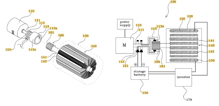
The peculiarity of this patent is that a static rotor with electromagnets controlled through a commutator-brush switching unit is attached to the generator stator where the winding is laid in grooves.

***


Solid-state Holcomb rotor, differs from these two patents noted above only by the electronic control system of the power electronics.


From these features comes the task for designing a solid-state synchronous generator machine.
 
A magnetic rotor is a permanent magnet or electromagnet that generates a permanent magnetic field at its poles. The magnetic rotor moves by moving a constant magnetic flux.
 
The task is to provide a constant magnetic flux between the poles of an electromagnet. Four magnetic flux loops [ϕ] are formed in the rotor/stator core of the four-pole design. The second task is to synchronously move the magnetic poles and looped magnetic fluxes [ϕ] for a complete revolution [] in the stator ring.
For small systems, you need to focus on repeating the rotor with permanent magnets, and not make a complex machine maintaining the industrial frequency and mains voltage at the output of the generator phase under load.

Thus, only one design is possible, it is a system of electromagnets that are constantly switched on to form a magnetic pole with a constant magnetic flux. The movement of the magnetic poles is organized by turning off and on two electromagnets in a chain of electromagnets that form the main magnetic pole.
For example, the main magnetic flux is formed by one pole, three electromagnets are formed, for a four-pole design (3 * 4 \u003d 12) electromagnets (6x6). To provide a zone for forming a window similar to a transformer one, we add one more electromagnet (12 + 4 = 16). To move the magnetic pole, the off magnet is turned on to form the sign of the approaching pole, and the closing one is turned off. Thus, an imitation of the rotation of a constant magnetic flux [Ф] consisting of four looped magnetic fluxes will be achieved

The plane of the pole piece of one electromagnet for the simplest design should cover the grooves where the phase wires of one phase are laid. If more or less slots are closed with one pole piece, then the effect will be weaker on the peak value of the EMF and, accordingly, on the current strength.

Traditional Rectifier Options for a Three-Phase Generator:


For such a configuration, it is effective to make a selection through a controlled rectifier to charge the battery of your household's power system. Which can very effectively replace or supplement a wind generator, mini hydroelectric power station or solar panels.
If you do a simplified version, then my recommendation is to isolate each phase through a rectifier diode bridge. The adjustment is made using a thyristor installed in the phase circuit in front of the diode bridge.

To understand how a synchronous alternator works, where the winding is in the slot or on the coil core, it is enough to consider the simplest synchronous alternator.  It does not matter what will cause the change of magnetic flux in the core, a mechanical magnetic rotor or a solid-state fixed solenoid switching system according to a given algorithm. 


The principle of this generator was provided by an unknown person who signed his letters with the letters [P.M.] to Michael Faraday, for his publication in the Royal Journal, of an article about his discovery of electromagnetic induction, when experimenting with an induction coil on a ring core. Michael Faraday did not understand how his discovery worked and discovered another principle, unipolar electromagnetic induction. In fact, all synchronous generators work on the basis of information provided by the unknown. Modern physicists can't answer exactly how this happens. Interesting stuff on a related topic at the link:  Your Electricity * Over Unity: Трансформатор с загадкой - "как"? (rakatskiy.blogspot.com)


*****

Best regards, Serge Rakarskiy!

Glory to Ukraine!
Glory to heroes!


2 коментарі:

newpassorg сказав...

i am following your posts which i consider them very informative , what about your book where we can find it ?

rakarskiy сказав...

Good time! The book "Electromagnetic Generator - Over Unity" is not yet ready. Everything takes time and money. Sincerely.